
I’ve wasted entire weekends because I skipped one tiny step during linear guide installation. One wrong torque sequence on a ball bearing carriage or a 0.03mm high spot can turn a $3,000 precision linear motion system into scrap metal within weeks. After installing over 200 linear guide systems across CNC machines, semiconductor equipment, and packaging lines, I’ve learned exactly what works and what fails.
You can install linear guides perfectly in one day if you follow just four critical phases: gather specialized alignment tools including 0.001mm dial indicators and calibrated torque wrenches, prepare a mounting surface flatter than 0.02mm/100mm following ISO 14253-1 standards, align rails to 0.01mm parallelism using the reference-driven method with systematic measurement grids, and finish with 24-hour thermal settling re-torque plus manufacturer-specified lubrication at precise quantities.
Keep reading—I’ll save you the expensive mistakes I made installing linear motion systems for over 15 years.
1. What Tools and Materials Do I Need Before Linear Guide Installation?
Skipping proper tools is the fastest way to ruin a Saturday and destroy expensive linear bearings. I once tried saving time by using a standard ruler instead of a dial indicator. The result? Both rails looked parallel to my eye, but the 0.08mm error I missed caused carriage binding within 500 operating hours.
Essential tools for precision linear guide installation: calibrated torque wrench set covering 2-50 Nm range with ±4% accuracy, 0.001mm resolution dial indicator with magnetic base rated at 50kg holding force, certified granite straight edge or precision level meeting Grade A specifications, 99% isopropyl alcohol and acetone, lint-free cleanroom wipes (Class 100 or better), stainless steel shim stock kit with 0.05mm, 0.10mm, 0.25mm, and 0.50mm thicknesses, and the exact NLGI Grade 2 grease specified by your linear rail manufacturer.

1.1 Critical Measurement Tools for Alighning Linear Rails
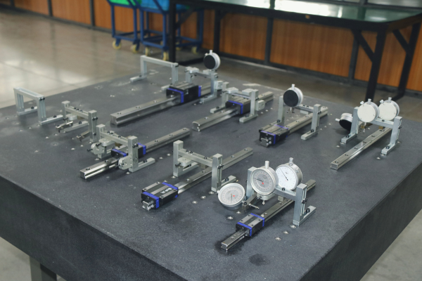
Your dial indicator becomes the most important tool when mounting linear rails. According to NIST dimensional metrology standards, you need at least 0.001mm (0.00004 inch) resolution to detect parallelism errors that cause premature bearing wear. I keep three indicators in my kit: one for surface flatness verification, another for rail-to-rail parallelism, and a backup because drops happen on job sites.
Here are the measurement tools I bring to every linear guide installation:
| Measurement Tool | Required Accuracy | Why You Can’t Skip It | Typical Cost Range |
|---|---|---|---|
| Dial indicator with magnetic base | 0.001mm resolution | Detects parallelism errors invisible to eye | $150-300 |
| Calibrated torque wrench set | ±4% accuracy per ISO 6789 | Prevents rail base distortion from over-torque | $200-500 |
| Precision spirit level | 0.02mm/m sensitivity | Establishes reference plane for multi-axis systems | $100-250 |
| Feeler gauge set | 0.01-1.00mm blade range | Verifies mounting surface flatness gaps | $20-50 |
| Precision straight edge (Grade A) | 0.005mm/300mm straightness | Reference for surface flatness measurement | $300-800 |
The DIN 645-1 standard specifies that linear guide mounting surfaces must achieve specific flatness tolerances based on accuracy class. For standard P5 precision guides commonly used in automation, you need surface flatness within 0.025mm per 160mm length. High-precision P3 guides require 0.012mm per 160mm—impossible to achieve without proper measurement tools.
1.2 Cleaning Supplies and Contamination Control
Linear bearing contamination is the number one cause of premature failure according to bearing manufacturer warranty data. Even a single metal chip measuring 0.1mm can score bearing raceways beyond repair. Your cleaning supplies determine whether your guides last their rated 50,000 km life or fail at 5,000 km.
I follow this exact contamination control sequence based on Society of Tribologists and Lubrication Engineers guidelines:
| Cleaning Step | Material Used | Purpose | Dwell Time |
|---|---|---|---|
| 1. Initial debris removal | Oil-free compressed air (5 micron filtered) | Removes loose particles and chips | 30 seconds per area |
| 2. Heavy oil removal | Acetone on lint-free wipes | Dissolves adhesives and machining oils | Wipe until cloth stays clean |
| 3. Final degreasing | 99% isopropyl alcohol | Removes residue without leaving film | Allow 60 seconds evaporation |
| 4. Fine particle removal | HEPA-filtered vacuum | Eliminates sub-visible particles | Full surface coverage |
| 5. Final verification | Tack cloth pass | Catches remaining contamination | Single light pass |
1.3 Fastener Selection and Bolt Grade Requirements
Don’t assume the bolts that come with your rails are sufficient for your application. The ISO 898-1 standard defines bolt property classes, and you need minimum Class 12.9 for linear guide mounting. These high-strength bolts provide 1200 MPa tensile strength and 1080 MPa yield strength—critical for maintaining clamping force under vibration and thermal cycling.
I once used standard Class 8.8 bolts from a hardware store to save $30. Three months later, the customer sent photos of loose rails and damaged carriages. The repair cost exceeded $2,000. Now I only use socket head cap screws meeting these specifications:
- Material: Alloy steel per ISO 898-1 Class 12.9 minimum
- Coating: Black oxide or zinc-nickel plated for corrosion resistance
- Thread engagement: Minimum 1.5 × bolt diameter in steel, 2.0 × in aluminum
- Washer requirement: Hardened flat washers (HRC 38-45) under all bolt heads
- Thread locker: Medium-strength (blue) on all mounting bolts
1.4 Shim Stock Kit Preparation
Proper shimming saves linear guide installations that would otherwise require expensive surface re-machining. Your shim stock kit should contain hardened stainless steel strips in multiple thicknesses. I carry these sizes in my field kit:
| Shim Thickness | Typical Application | Maximum Coverage Area | Material Specification |
|---|---|---|---|
| 0.05mm | Fine parallelism adjustment | 10% of rail base width | 302 stainless steel, hardened |
| 0.10mm | Minor surface low spots | 15% of rail base width | 302 stainless steel, hardened |
| 0.25mm | Moderate corrections | 20% of rail base width | 302 stainless steel, hardened |
| 0.50mm | Significant surface irregularities | Edge-only application | 302 stainless steel, hardened |
Critical rule: Never stack more than two shims at any location. If you need more correction than 0.6mm total, the mounting surface requires machining. Stacked shims compress unevenly under load, creating instability that worsens over time.
2.How Should I Prepare My Mounting Surface for the Rails?
This preparation phase determines 70% of installation success. Everything else is just tightening bolts correctly. I’ve seen engineers spend hours on alignment only to discover their mounting surface had a 0.1mm wave that made proper alignment impossible.
Your mounting surface must achieve flatness within 0.02mm per 100mm per ASME Y14.5 geometric tolerancing standards, be completely free of contamination including fingerprints, and have reference edges perpendicular to within 0.01mm over the guide length. Surface roughness should not exceed Ra 3.2 micrometers for optimal rail-to-base contact and maximum load distribution.
2.1 Step-by-Step Surface Flatness Measurement
You can’t fix what you don’t measure. I create a complete surface map before mounting any rails. This takes 30 minutes but saves days of troubleshooting later. Here’s my exact measurement procedure:
Step 1: Establish measurement grid. Divide your mounting surface into a grid based on rail size. For rails under 500mm, measure every 50mm along the length. Measure every 100mm for rails 500-1500mm, while for rails over 1500mm, measure every 150mm. Always measure at three points across the width: both edges and center.
Step 2: Position straight edge. Place your certified Grade A straight edge along the intended rail path. Use adjustable stands to elevate the straight edge 0.5mm above the surface at one end—this allows feeler gauge insertion.
Step 3: Take measurements. At each grid point, insert progressively thicker feeler gauge blades until you find the one that just fits with light drag. Record this value on your measurement map.
Step 4: Identify problem areas. Any location exceeding your tolerance (typically 0.02mm/100mm for automation applications) requires correction before proceeding.
| Rail Size Category | Measurement Interval | Flatness Tolerance | Typical Application |
|---|---|---|---|
| 15-25mm rail width | Every 50mm | 0.01mm/100mm | Semiconductor, metrology equipment |
| 30-45mm rail width | Every 100mm | 0.02mm/100mm | CNC machines, general automation |
| 55mm and larger | Every 150mm | 0.03mm/100mm | Heavy machinery, material transfer |
2.2 Surface Correction Methods and When to Use Each
When you find areas exceeding flatness tolerance, you have three correction options. Each method has specific use cases and limitations based on my field experience:
Hand scraping for precision correction (0.01-0.05mm removal): This traditional technique requires skill but provides excellent surface finish. I learned from a Japanese master technician who could achieve 0.003mm flatness over 500mm length. Use a carbide-tipped hand scraper with 25mm wide blade. Apply light pressure, scrape in consistent patterns (typically diagonal crosshatch), and check progress with engineer’s blue every 10-15 strokes. The key: take light passes and check frequently with your straight edge.
Precision grinding for larger corrections (0.05-0.5mm removal): Use a surface grinder if available, or carefully use an angle grinder with a precision cup wheel for field work. Critical warning: grinding generates heat that can warp your base material. Take 0.01mm passes maximum and allow 5-minute cooling between passes. Check flatness after every pass to avoid removing too much material.
Strategic shimming for low spots (0.02-0.3mm compensation): When grinding isn’t possible, shimming can compensate for low areas. Follow these rules strictly:
- Place shims only at rail base edges (maximum 20% of base width from each side)
- Never shim under full rail base width—this creates a rocking pivot point
- Use hardened stainless steel shims only—soft materials compress under load
- Limit to two stacked shims maximum at any location
- Secure shims with light adhesive to prevent shifting during bolt tightening
2.3 Reference Edge Verification Procedure
Your mounting surface reference edges guide rail positioning. These edges must meet stringent perpendicularity requirements or your entire system develops angular errors that compound across the travel length. Here’s my verification procedure:
First: Clean reference edges thoroughly with acetone to remove any burrs or debris.
Then: Place a certified machinist square (accuracy: 0.005mm per 100mm minimum) against the primary reference edge with the blade extending along the secondary edge.
Third Step: Use a 0.01mm feeler gauge to check for gaps between the square blade and secondary edge. Check at three positions: start, middle, and end of rail path.
At last: Document any deviations. Errors exceeding 0.01mm over rail length require correction before mounting rails—either by machining the reference edge or by using precision dowel pins as alignment references instead.
2.4 Final Surface Cleaning Protocol
After all corrections, perform final cleaning immediately before rail placement. The surface must be completely free of:
- Metal chips from grinding or scraping operations
- Dust and airborne particles
- Fingerprint oils (contain acids that promote corrosion)
- Residual cutting fluids or rust preventatives
- Adhesive residue from tape or labels
Follow the five-step cleaning sequence I described earlier. Do not touch the cleaned surface with bare hands—use clean nitrile gloves when positioning rails. A single fingerprint can cause visible corrosion on bare steel within 48 hours in humid conditions.
3. How Can I Correctly Mount and Align the Reference and Driven Rails?
This alignment phase is where most installations fail—and where precision pays off for years of reliable operation. I’ve seen systems where rails looked perfectly parallel to the eye but measured 0.08mm out of specification. That 0.08mm caused carriage binding within 500 hours of operation.
Reference rail installation establishes your primary datum using a three-stage torque sequence (30%-60%-100%) in crisscross pattern per VDI 2230 bolted joint guidelines. Driven rail alignment requires achieving parallelism within 0.01mm over full length using carriage-mounted dial indicators, with adjustments made through controlled tapping or edge shimming before final torque application to prevent stress-induced deformation.
3.1 Selecting and Positioning the Reference Rail
Your reference rail becomes the datum for every other component in your system. Rail selection matters—even new rails from the same batch can have slight straightness variations. I measure each rail on a surface plate (or using the mounting surface if no surface plate is available) to identify straightness within 0.005mm/meter. Choose the straightest rail as your reference rail.
Position the reference rail along your reference edge, maintaining consistent gap of 0.5-1.0mm between rail side and reference edge. This gap allows for thermal expansion—steel expands approximately 0.012mm per meter per degree Celsius. A 1-meter rail in an environment with 20°C temperature swings can grow or shrink by 0.24mm. Without clearance, thermal expansion causes rail bowing and bearing damage.
Use precision alignment fixtures or small magnetic clamps to hold the rail in position before bolting. These temporary fixtures should not obstruct any bolt holes and must be removable after final tightening.
3.2 Three-Stage Torque Sequence for Reference Rail
The bolt tightening sequence determines whether your rail stays straight or develops waves that cause carriage binding. Number your mounting holes mentally from 1 to N. For a rail with 8 bolts, tighten in this exact sequence: 4-5-3-6-2-7-1-8 (center outward, alternating sides). This distributes clamping force evenly and prevents rail distortion.
Three-stage torque application prevents sudden stress that can crack rail bases or cause micro-shifting:
Stage 1 (30% of final torque): Apply hand-tight plus approximately 1/4 turn to each bolt following the crisscross sequence. This seats the rail against the mounting surface without inducing significant stress. Check rail position with dial indicator after completing all bolts—maximum acceptable lateral movement is 0.01mm from original position.
Stage 2 (60% of final torque): Apply half of the manufacturer’s specified torque value to each bolt, again following crisscross sequence. Re-check rail position and straightness. If any position has shifted more than 0.005mm, loosen that bolt and adjacent bolts, reposition, and re-tighten.
Stage 3 (100% of final torque): Apply full manufacturer specification torque. Typical values range from 8-25 Nm depending on bolt size and rail model. Use a calibrated torque wrench—guessing leads to either loose bolts that vibrate free or over-torqued bolts that crack rail bases.
| Rail Size (Width) | Typical Bolt Size | Stage 1 Torque | Stage 2 Torque | Final Torque |
|---|---|---|---|---|
| 15mm | M4 | 1.0 Nm | 2.0 Nm | 3.5 Nm |
| 20mm | M5 | 2.0 Nm | 4.0 Nm | 7.0 Nm |
| 25-30mm | M6 | 3.5 Nm | 7.0 Nm | 12 Nm |
| 35-45mm | M8 | 7.0 Nm | 14 Nm | 25 Nm |
| 55mm+ | M10 | 12 Nm | 25 Nm | 45 Nm |
3.3 Setting Up Dial Indicator for Parallelism Measurement
Driven rail alignment separates professional installations from amateur attempts. You need a measurement setup that travels along the reference rail while measuring distance to the driven rail. Here’s exactly how to build this setup:
Step 1: Mount a carriage on the reference rail temporarily. This carriage must slide freely across the full rail length without binding.
Step 2: Attach a magnetic base to the carriage. The magnetic base should have at least 50kg holding force to prevent indicator movement during measurement travel.
Step 3: Position your dial indicator in the magnetic base with the probe oriented perpendicular to the driven rail’s side reference surface. The probe should contact the rail approximately 10mm below the top edge—this is the most consistent reference surface.
Step 4: Ensure adequate probe travel. Set the indicator with approximately 0.5mm preload so it can measure both positive (rails diverging) and negative (rails converging) deviations from the zero point.
3.4 Systematic Parallelism Measurement and Adjustment
With your measurement setup complete, follow this proven procedure that works reliably for rails up to 4 meters long:
Step 1: Initial positioning. Position the driven rail approximately parallel using visual references. The goal is to get within 0.5mm of parallel before fine adjustment.
Step 2: Zero reference. Move the indicator carriage to one end of the reference rail (I always start at the same end for consistency). Zero the dial indicator with the probe touching the driven rail.
Step 3: Full-length survey. Slowly slide the carriage along the reference rail while recording indicator readings every 200mm. Write these values on a measurement map or directly on tape alongside the mounting surface.
Step 4: Identify maximum deviation. Your measurement map shows exactly where the rails diverge or converge. The point with the largest absolute deviation is where you make your first adjustment.
| Position Along Rail | Indicator Reading | Deviation Status | Required Action |
|---|---|---|---|
| 0mm (start) | 0.000mm | Zero reference | Reference point established |
| 200mm | +0.006mm | Within tolerance | No action needed |
| 400mm | +0.014mm | OUT OF SPEC | Tap rail inward 0.01mm |
| 600mm | +0.008mm | Within tolerance | Monitor after 400mm correction |
| 800mm (end) | +0.004mm | Within tolerance | Good final position |
Step 5: Make adjustment. Use a soft-faced mallet (brass or plastic) to tap the driven rail at the location of maximum deviation. For the example above, the +0.014mm reading at 400mm means the rails are diverging—tap the driven rail toward the reference rail. Expect approximately 0.002-0.005mm movement per controlled tap.
Step 6: Re-measure and repeat. After each adjustment, re-survey the full length. Adjustments at one location affect neighboring areas because the rail is semi-rigid. You may need 3-5 adjustment cycles to achieve consistent parallelism within 0.01mm across all measurement points.
3.5 Final Torquing of Driven Rail
Once parallelism is within specification at all measurement points, secure the driven rail using the same three-stage crisscross torque sequence as the reference rail. Critical step: Re-check parallelism after Stage 2 (60% torque). Tightening bolts can shift the rail slightly—I’ve measured up to 0.012mm lateral movement during final torque application.
If parallelism has degraded after Stage 2 torque, you must loosen bolts and re-adjust. This is frustrating but absolutely necessary. Proceeding with out-of-spec parallelism guarantees premature wear and potential bearing failure.
4. What Final Adjustments and Lubrication Do I Need to Perform?
You’re 95% complete—these final steps determine whether your system delivers 10 years of reliable service or fails within 10 months. I’ve seen engineers skip the 24-hour re-torque step and wonder why bolts vibrated loose within 6 months of operation.
Final adjustments include mandatory 24-hour settling period re-torque to compensate for stress relaxation per AISC bolted joint specifications, application of manufacturer-specified NLGI Grade 2 lithium-based grease at 0.5-1.5 grams per lubrication point until fresh grease emerges at seals, controlled break-in operation at 30% speed for minimum 2 hours, and verification that cable management systems maintain 20mm minimum clearance throughout full carriage stroke including both extreme positions.
4.1 The Critical 24-Hour Settling Period
Material stress relaxation is real physics, not optional waiting time. When you torque bolts to specification, the clamping force induces stress in multiple materials simultaneously: bolt shaft tension, thread contact stress, rail base compression, and mounting surface deformation. Over 24 hours, these stresses redistribute through microscopic material movement (creep), reducing effective clamping force by 5-15%.
Temperature cycling accelerates this process dramatically. A 10°C ambient temperature change causes steel to expand or contract by 0.12mm per meter. This thermal movement works bolted joints repeatedly, accelerating stress relaxation. Schedule your re-torque for the same approximate time of day and ambient temperature as initial installation to minimize thermal variables in your measurements.
During re-torque, expect to find 20-30% of bolts requiring additional rotation to reach specified torque. This is normal, not an installation error. Document which bolts needed adjustment—patterns can reveal mounting surface irregularities you missed during preparation. For example, if all bolts on one side of the rail needed re-torque but the other side didn’t, you may have a slight surface crown that’s causing uneven clamping.
4.2 Precision Lubrication Application Procedure
Linear guides operate under extreme tribological conditions. Ball or roller bearings experience Hertzian contact stress exceeding 2000 MPa at the ball-raceway interface—higher than most materials’ yield strength. Without proper lubrication, these contact points develop microscopic welding (adhesive wear) within hours of dry operation.
Your manufacturer specifies exact lubricant type for engineering reasons based on their bearing geometry and materials. The base oil viscosity, thickener type, and additive package all affect performance and service life. Common specifications include:
| Lubricant Type | NLGI Grade | Operating Temperature | Best Application |
|---|---|---|---|
| Lithium complex grease | NLGI 2 | -30°C to +120°C | General industrial automation |
| Calcium sulfonate grease | NLGI 2 | -20°C to +150°C | Washdown environments, high moisture |
| Synthetic PFPE grease | NLGI 2 | -70°C to +200°C | Clean room, semiconductor |
| Food-grade H1 lubricant | NLGI 2 | -20°C to +120°C | Food processing, pharmaceutical |
Grease application technique: Connect your grease gun to the carriage grease nipple (Zerk fitting). Apply grease using slow, steady pump strokes. Fast pumping creates hydraulic pressure that can blow out carriage seals—I learned this the hard way when I destroyed a $400 carriage with over-aggressive greasing. Continue pumping slowly until you see a thin bead of fresh grease emerge from the carriage lip seals. This confirms complete filling of all internal grease passages and displacement of old, contaminated lubricant.
4.3 Controlled Break-In Procedure
New linear guides benefit from controlled break-in operation. Fresh linear bearing surfaces have microscopic high points that must polish smooth through controlled operation. So, this break-in process creates a conformal surface that reduces friction and extends bearing life. Run this exact break-in sequence:
- Hours 1-2: Operate at 30% of maximum rated speed with no payload. Monitor for any unusual sounds or binding.
- Hours 3-4: Increase to 50% speed with 25% of rated load capacity.
- Hours 5-8: Operate at 75% speed with 50% of rated load.
- Hours 8+: Full speed and load operation permitted.
Monitor carriage bearing temperature during break-in using a non-contact infrared thermometer. Normal temperature rise: 5-10°C above ambient. Warning level: 15-20°C rise—reduce speed and check lubrication. Critical: >25°C rise indicates severe problem such as misalignment, contamination, or inadequate lubrication—stop operation immediately and investigate.
4.4 Establishing Your Maintenance Schedule
Create a maintenance schedule based on your actual operating conditions, not generic manufacturer recommendations. The DIN 637 standard provides baseline intervals, but adjust based on your specific environmental and operational factors:
| Operating Environment | Speed/Load Level | Re-lubrication Interval | Full Inspection Interval |
|---|---|---|---|
| Clean room (Class 100-10000) | Low speed, light load | 12 months | 12 months |
| Standard factory environment | Medium speed and load | 3 months | 6 months |
| Dusty, humid, or outdoor | Any speed/load | 1 month | 3 months |
| Any environment | High speed or heavy load | 2 weeks | 1 month |
| 24/7 continuous operation | Any | Consider automatic lubrication | Monthly monitoring |
4.5 Documentation for Future Reference
Create comprehensive installation documentation before you leave the job site. This package becomes invaluable during troubleshooting, warranty claims, and training new maintenance personnel. Include:
- Photographs of completed installation from multiple angles with scale reference
- Surface flatness measurement map with all recorded values
- Final parallelism measurements at each check point
- Torque values applied to each bolt position
- Shim locations, thicknesses, and placements if any were used
- Ambient temperature during installation
- Rail and carriage serial numbers and their installed positions
- Lubricant type, quantity applied, and next lubrication date
- Cable routing documentation and clearance verification
5. Conclusion
Perfect linear guides installation requires discipline, proper measurement tools, and also need your attention to details that most people overlook. Follow these procedures exactly as written—from surface preparation through final lubrication, so your system will deliver reliable precision motion for years beyond its rated service life. The 4-6 hours you invest in proper installation saves weeks of troubleshooting and thousands of dollars in premature replacement costs.
👉 Related IMTEK Products: